
Common Faults and Solutions for Micropilot Non-Contact Radar and Levelflex Guided Wave Radar (FMR/FMP Series)
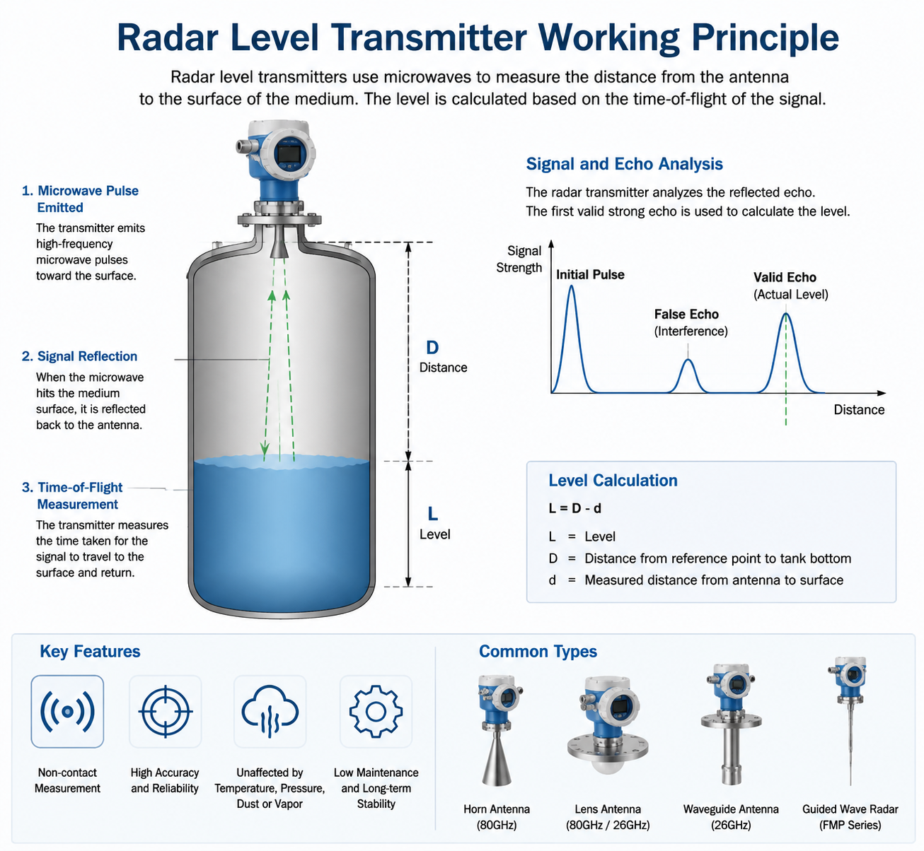
Endress+Hauser radar level transmitters, including Micropilot non-contact radar and Levelflex guided wave radar, are widely used in oil & gas, chemical, water treatment, food, and process industries.
Although radar level instruments are known for high reliability, measurement problems may occur due to incorrect installation, unsuitable parameter settings, harsh process conditions, or hardware failures.
This article provides a practical troubleshooting guide for common radar level transmitter problems and recommended solutions.
1. Basic Checks Before Troubleshooting
Before performing detailed troubleshooting, always check the basic conditions first.
1.1 Power Supply and Communication
Typical E+H radar level transmitters use:
- Power supply: 24 VDC (two-wire loop powered)
- Output: 4–20 mA / HART
- Optional communication:
- PROFIBUS PA
- FOUNDATION Fieldbus
- Modbus
- Other digital communication interfaces depending on model
Common commissioning and diagnostic tools include:
- SmartBlue App
- FieldCare
- DeviceCare
- HART communicator
- PACTware
1.2 General Troubleshooting Sequence
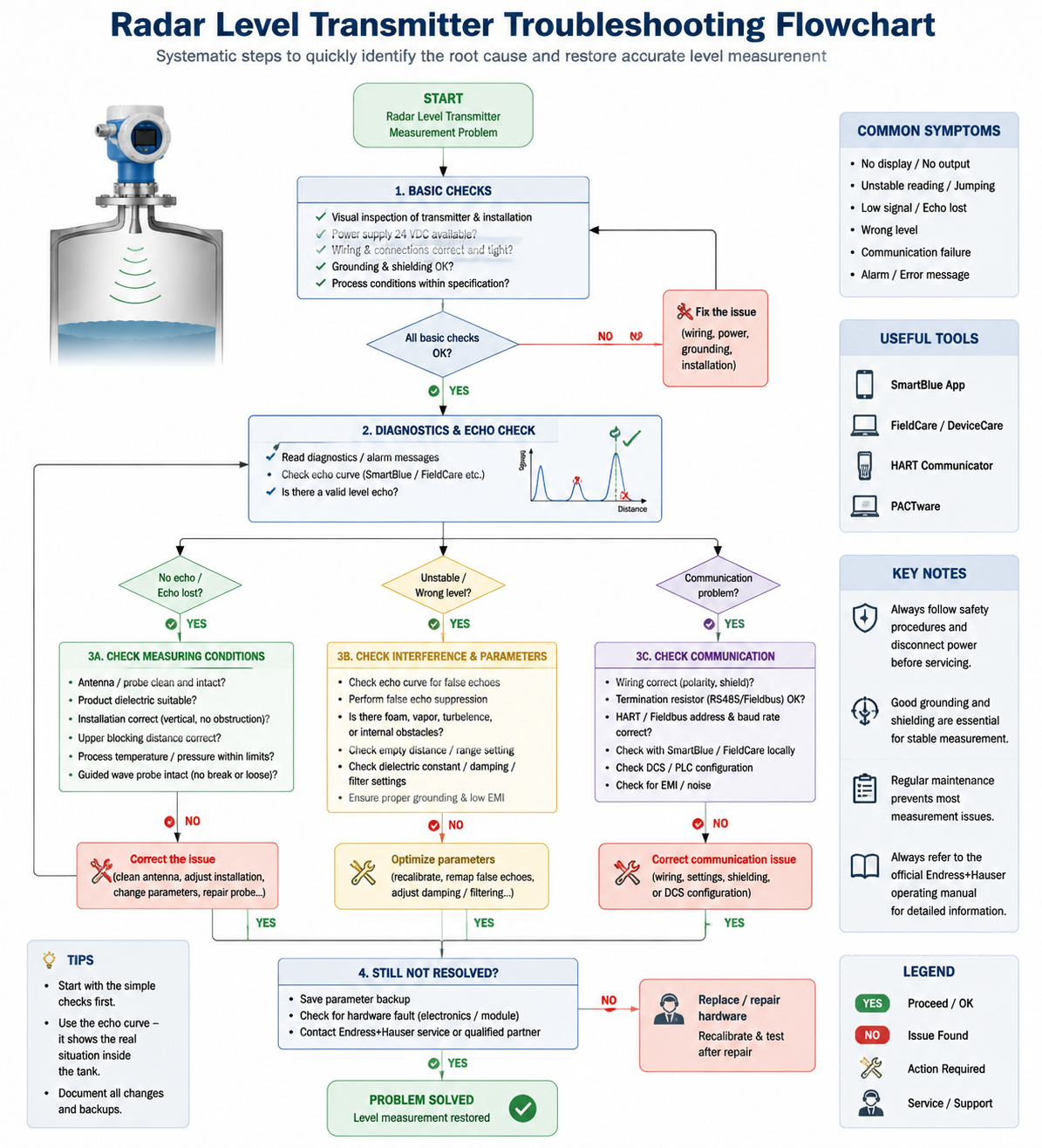
A recommended troubleshooting order:
Power supply and wiring → Process conditions → Parameter configuration → Echo analysis → Hardware inspection
This prevents unnecessary replacement of electronic components.
For hazardous areas:
- Follow applicable explosion protection regulations.
- Disconnect power before opening the device.
- Follow lockout/tagout procedures when required.
1.3 Wiring and Installation Checks
Important installation points:
- Ensure correct polarity and stable power supply.
- Use suitable shielded cables.
- Follow local grounding requirements.
- Keep signal cables away from:
- Motor cables
- Variable frequency drives (VFD)
- High-power electrical equipment
Poor installation can cause unstable signals or communication problems.
2. Preventive Maintenance Recommendations
Regular maintenance can significantly improve radar measurement reliability.
2.1 Inspect Antenna and Probe Condition
Check regularly for:
- Product buildup
- Condensation
- Corrosion
- Mechanical damage
- Loose connections
For cleaning:
- Use suitable cleaning methods.
- Avoid scratching PTFE, ceramic, or coated antenna surfaces.
2.2 Check Echo Curve and False Echo Suppression
Radar measurement depends on reliable echo evaluation.
Recommended actions:
- Review the echo curve periodically.
- Perform false echo mapping when required.
- Verify that internal tank structures are correctly identified.
2.3 Check Mechanical Installation
Inspect:
- Flange sealing
- Gaskets
- Process connections
- Instrument housing condition
Prevent moisture or process media from entering the electronics compartment.
2.4 Backup Parameters
After commissioning:
- Save configuration parameters.
- Keep backup files for future replacement or troubleshooting.
3. Common Radar Level Transmitter Problems and Solutions
Problem 1: No Display, No Output, or Device Does Not Start
Possible Causes
- Incorrect power supply voltage
- Reverse polarity wiring
- Loose or oxidized terminals
- Damaged power module
- Water ingress inside electronics housing
- Electronic module failure
Recommended Solutions
- Measure the supply voltage and verify correct wiring polarity.
- Check terminal connections and repair damaged cables.
- Inspect housing seals and check for condensation or water ingress.
- Dry and inspect the electronics compartment if moisture is found.
- If electronic modules fail, follow the manufacturer’s service procedure for replacement.
Problem 2: Unstable Measurement, Level Jumping, or Incorrect Reading
Possible Causes
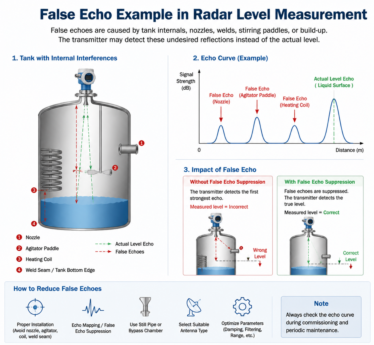
- False echoes from:
- Tank nozzles
- Internal pipes
- Heating coils
- Tank supports
- Weld seams
- Foam or vapor interference
- Strong agitation or turbulence
- Low dielectric constant medium
- Incorrect parameter settings
- Poor installation position
- Electromagnetic interference
Recommended Solutions
1. Check Echo Curve
Use diagnostic software to:
- Analyze echo quality.
- Identify interference signals.
- Perform false echo suppression.
2. Improve Installation Conditions
Avoid installing the radar:
- Directly above filling points
- Near strong turbulence
- Close to internal obstacles
For difficult applications:
- Use suitable antenna designs.
- Consider stilling wells or bypass chambers.
3. Optimize Parameters
Check:
- Empty tank distance
- Measuring range
- Medium properties
- Damping/filter settings
Adjust parameters according to actual process conditions.
4. Check Grounding and Electrical Noise
Inspect:
- Cable shielding
- Grounding
- Nearby electrical interference sources
Keep instrument cables away from high-power equipment.
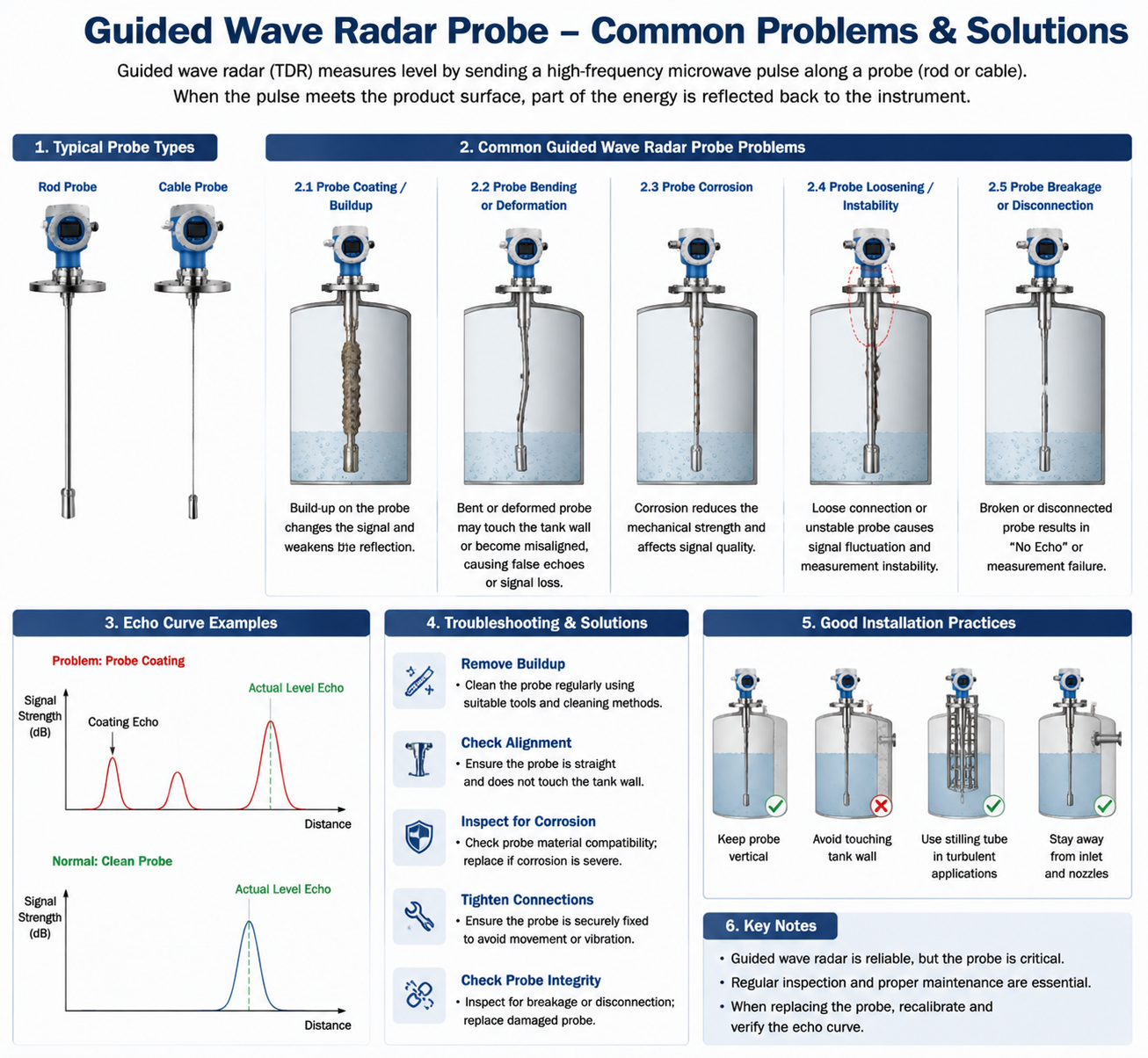
5. Check Guided Wave Radar Probe
For Levelflex radar:
Inspect:
- Probe connection
- Rod/cable damage
- Mechanical bending
- Corrosion
Problem 3: Weak Signal, Echo Lost, or No Measurement Signal
Possible Causes
- Dirty antenna
- Condensation on antenna
- Damaged antenna
- Low dielectric constant product
- Incorrect installation
- Temperature or pressure exceeding limits
- Broken guided wave probe
Recommended Solutions
- Clean the antenna carefully and inspect for damage.
- For low dielectric products:
Consider:
- Guided wave radar
- Still pipe installation
- Optimized antenna selection
- Check:
- Operating temperature
- Pressure rating
- Upper blocking distance settings
- Verify vertical installation and avoid tank structures blocking the radar signal.
Problem 4: Communication Failure (4–20mA / HART / Fieldbus)
Possible Causes
- Incorrect wiring
- Incorrect communication parameters
- Wrong device address
- Missing termination resistor (for applicable bus systems)
- Electromagnetic interference
- Communication module failure
Recommended Solutions
- Check communication wiring and polarity.
- Verify:
- HART address
- Bus parameters
- Baud rate
- Protocol settings
- Connect locally using SmartBlue or configuration tools to confirm instrument status.
- Check DCS/PLC configuration.
- Improve cable shielding and grounding.
Problem 5: Diagnostic Alarm or Error Message
Recommended Troubleshooting Steps
- Read diagnostic information through:
- Local display
- SmartBlue
- FieldCare
- DeviceCare
- Check the corresponding error code in the operating manual.
- For configuration-related alarms:
- Restore correct parameters.
- Perform recalibration.
- For hardware alarms:
Examples:
- Sensor failure
- Electronic module failure
Contact qualified service personnel.
- For temperature alarms:
Check:
- Actual process temperature
- Insulation
- Cooling or heating requirements
Problem 6: Water Leakage, Flange Leakage, or Corrosion Damage
Possible Causes
- Aging gasket
- Incorrect flange tightening
- Improper material selection
- Corrosive process conditions
Recommended Solutions
- Replace damaged sealing components with suitable materials.
- Tighten flange bolts evenly using proper procedures.
- For corrosive applications:
Confirm compatibility of:
- PTFE
- Ceramic
- Tantalum
- Hastelloy
- Other corrosion-resistant materials
- If water enters the electronics housing:
Disconnect power immediately and inspect the electronics.
4. Radar Level Transmitter Calibration and Parameter Settings
Correct configuration is essential for accurate measurement.
Empty Tank Calibration
Confirm:
- Reference distance
- Tank height
- Zero point
Full Tank Calibration
Compare:
- Radar measurement value
- Manual level measurement
Adjust calibration if required.
False Echo Suppression
For tanks with fixed internal structures:
- Perform false echo mapping.
- Create a reference echo profile.
Medium Parameters
Optimize:
- Dielectric constant
- Damping
- Filtering parameters
according to process conditions.
Parameter Backup
Always save final configuration after commissioning.
5. Maintenance and Repair Recommendations
Recommended Practices
- Use compatible replacement parts.
- Verify antenna, probe, and electronic modules match the instrument model.
- Perform recalibration after major component replacement.
Important Safety Notes
Do not:
- Open equipment in hazardous areas without proper authorization.
- Remove electronics while energized.
- Modify explosion-proof components.
Incorrect maintenance may affect:
- Measurement performance
- Safety certification
- Product warranty
6. Application Recommendations
High Temperature or Steam Applications
Recommended solutions:
- Select suitable antenna design.
- Use thermal insulation.
- Prevent condensation.
Dusty or Sticky Materials
Recommended solutions:
- Regular antenna inspection.
- Use suitable antenna types.
- Consider purge systems if required.
Explosion-Proof Areas
Confirm:
- Correct Ex certification
- Proper cable installation
- Compliance with local regulations
7. Troubleshooting Information Checklist
When requesting technical support, provide:
Instrument Model:
Serial Number:
Application:
Medium:
Operating Temperature / Pressure:
Alarm Message:
Echo Curve Status:
Power Supply and Wiring Condition:
Actions Already Taken:
8. Conclusion
Most radar level transmitter problems are caused by:
- Incorrect installation
- Poor parameter configuration
- Process interference
- Insufficient maintenance
A systematic troubleshooting approach can quickly identify the root cause and avoid unnecessary replacement.
For Endress+Hauser Micropilot or Levelflex radar level transmitter replacement, application evaluation, or compatible solutions, our engineering team can provide technical support based on your process requirements.